

Products & Applications
PRODUCTS

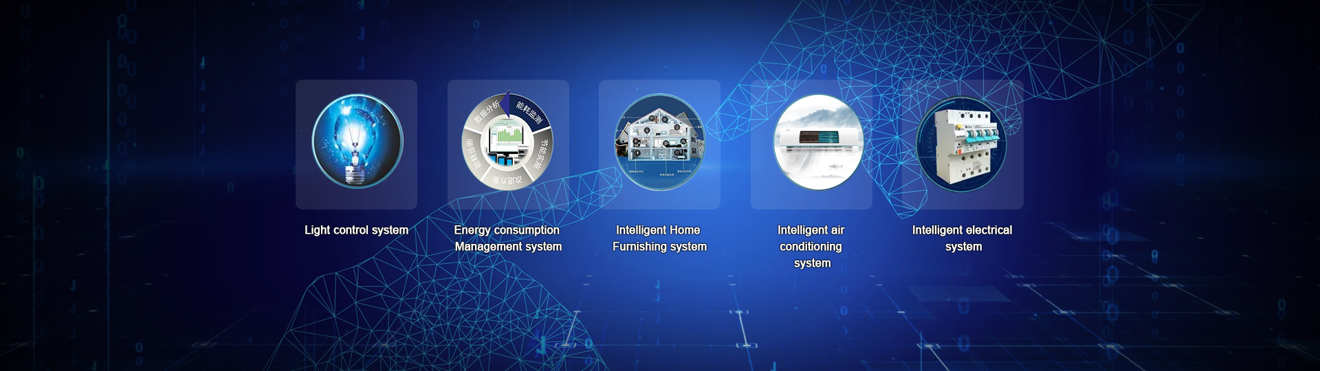
DALI Dimming System
Location Position:Home > Products & ApplicationsDALI-RS485 module RGB color temperature control
1 Overview of product functions:
DALI DK2000-DALI0216M is a controller with functions of single lamp control, scene mode control, timing control, longitude and latitude control, illumination control and human body induction control. It comes with LCD Chinese display interface, no programming, menu setting, comes with 2 DALI signal control ports, can be hung up to 64+64 lamps; In addition, it comes with 2 strong current control ports and built-in 50A high power magnetic holding relay, which can control the power supply of lamps and lanterns, making users safer and more assured. Supports open communication protocol networking through RS485 MODBUS RTU, TCP/IP and other national standards to achieve remote centralized management of computer and mobile APP.
2 Product Specifications and technical parameters:
Power supply/consumption: DC 24V / 15VA
Environment/Use: -25 to 60°C; 10 to 85% RH
Storage environment: -25 to 80 °C; Less than 90% RH
Man-machine interface: 12864LCD screen "menu/confirm", "up", "down", "left" and "right" buttons
Microprocessor: ARM series single chip microcomputer
Independent monitoring application software is available to upload different application software according to different control requirements
Have the ability of self-diagnosis, real-time monitoring of the controller and lamps, and upload to the host computer, to achieve centralized control
A battery-free program memory device (EEPROM) can store all operating programs to prevent data loss in the event of power failure.
All have extended FLASH, convenient system upgrade.
The guard dog device automatically resets.
DALI Output: 2 DALI outputs, 64+64 DALI lamps.
Relay output: High power 50A magnetic holding relay.
Communication mode: 1xRS-485 1/2 duplex/Modbus RTU Protocol
Communication rate: 9600~76.8k bps (factory/recommended 9600 bps)
Maximum communication distance: 4000 ft (1.2 km) To ensure communication reliability, it is recommended that the communication distance be smaller than 600 m
Communication signal input: RS485 Modbus RTU
Address setting range: A maximum of 16, that is, a panel can be connected to a maximum of 16 controllers
Signal connection head: 5PIN terminal
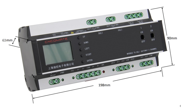
Appearance size: 198(W)*90(H)*63(D)
Installation: Standard DIN35 electric track
Weight: 0.65Kg
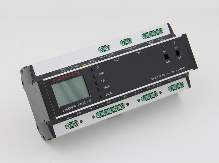
3 Product shell size and labeling
4 Keys and wiring instructions
4-1 Monochrome brightness adjustment wiring diagram:

4-2 Wiring diagram for color temperature regulation:

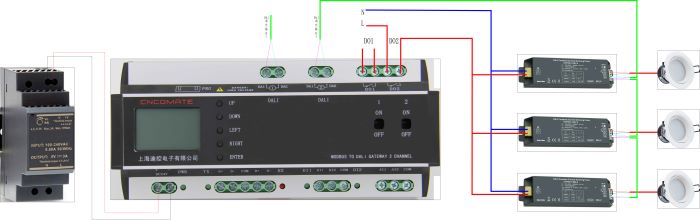
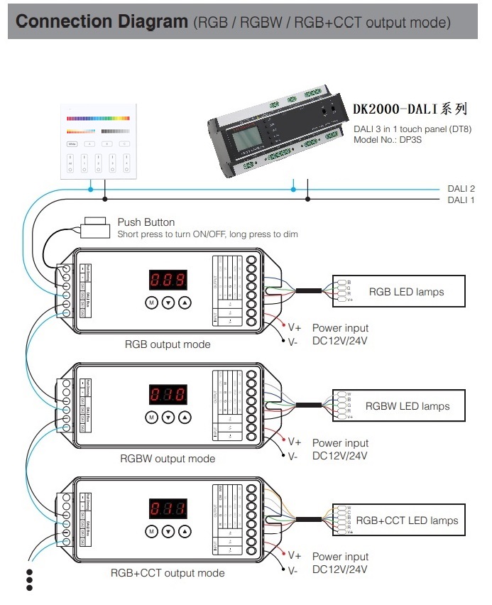
4-3 RGB color adjustment wiring diagram:
4-4 Button description:

|
DK2000-DALI0216M Controller hardware description |
|||
|
project |
name |
function |
remarks |
|
1 |
LCD screen |
Man-machine interface, display and set related functions |
Chinese menu interface, no programming |
|
2 |
Press Up |
Adjust the value/status of a set parameter |
|
|
3 |
Press Down |
|
|
|
4 |
Key Left |
Move the menu and select the desired menu item |
|
|
5 |
Key Right |
|
|
|
6 |
Press Enter |
The 'Confirm' button, when a menu or option is selected, will be backfired. |
|
|
7 |
The manual forced circuit back fails |
On-loop forced closure; OFF- The loop is forcibly disconnected |
To ensure safe operation, use a tool such as a driver |
|
8 |
Wiring terminal 24+, 24- |
Power DC24V input |
Power Power indicator. The indicator is on during normal operation |
|
9 |
Two groups of wiring terminals communicate D+,D-, and GND |
RS485 communication cable. D+ is connected to the communication line; D- Connects to the communication cable negative,GND grounding, one group of incoming wires, one group of outgoing wires. |
Tx and Rx indicators. When the communication is normal, the two indicators blink |
|
10 |
Wiring terminals DI1, DI2, COM |
Passive switch input DI1,DI2, COM is the common terminal. |
Can be connected to the human body sensor detector to realize people to light up, people walk delay light off. |
|
11 |
Terminal AI1,AI2,AIG |
Analog signal input AI1,AI2, AIG is the common end. Input sources can be 0-10v,4-20mA, or NTC sources. |
Illuminance sensor and other analog signals can be connected to achieve automatic illuminance control. |
|
12 |
Wiring terminals DA1,DA2 |
Two DALI signal outputs |
Each DALI connects to a maximum of 64 addresses |
|
13 |
Terminal DO1,DO2 |
2 loop switch output, built-in 2 50A magnetic holding relays |
Used to physically cut off the power supply, more secure |
5 System architecture diagram

For more details and setting instructions, please consult our customer staff.