


Products & Applications
PRODUCTS

Magnetic holding relay module
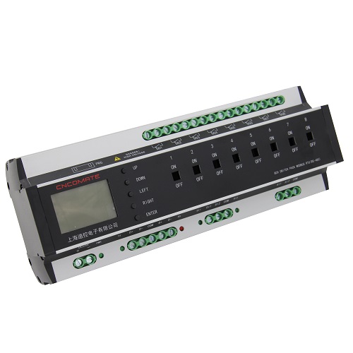
Location Position:Home > Products & Applications8-circuit 25A magnetic hold lighting switch module DK2000-CSN0825M
Product introduction
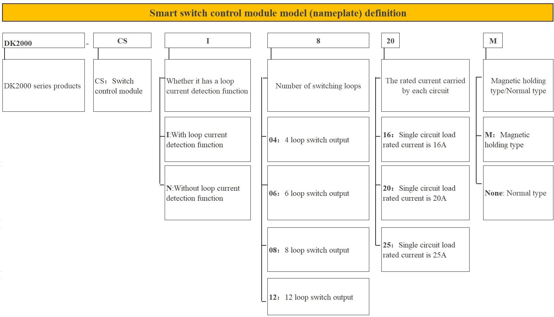
2-1 DK2000-CSX xx xxx series switch controller products

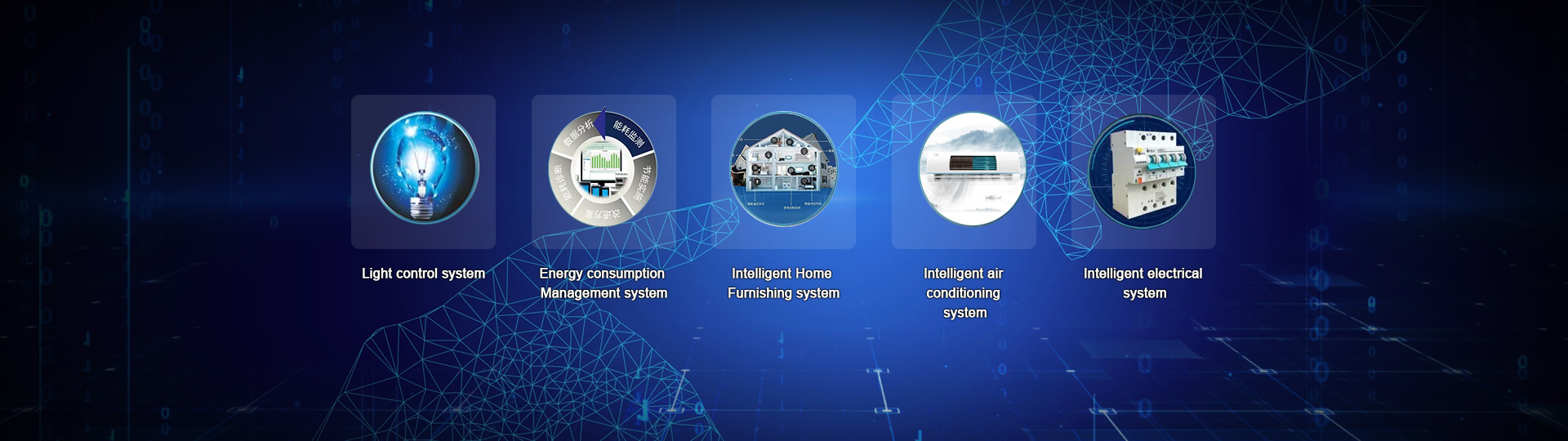
Architecture diagram of intelligent lighting control system
2-2 Product Function overview
DK2000-CS****M is a product with LCD Chinese display interface, programming free, menu setting, and independent use of intelligent lighting control module, it adopts imported 50A magnetic holding relay, itself low power consumption, small heat, but also can maintain the original output state after power off. Each relay comes with a mechanical handle. Even if the module fails unexpectedly, it can also realize the manual forced switch of the lighting circuit through the mechanical handle. It is a switching control module designed specifically for the currently widely used LED lights, outdoor high-power lamps and motor loads, which can resist instantaneous surge current up to 500A. It effectively solves the problem that the lamp can not be turned off due to the stickiness of relay contacts which is common in the market. It can provide safe and reliable intelligent control for the lighting system of important public places such as hospitals, stations, airports, stadiums, hotels, large shopping malls and so on.
Through RS485 MODBUS RTU, TCP/IP and other national standards open communication protocol networking, to achieve the remote centralized management of computer, mobile APP.
It can also combine with Shanghai DI Control cloud platform, and realize wireless communication management of each intelligent lighting control module through 4G signal transceiver module (DTU), which is very suitable for outdoor lighting system, old building lighting system transformation, home intelligent control and so on.
The main functional features are as follows:
1. All Chinese LCD display: menu type Chinese interface, so that you can combine the function keys, very convenient for parameter setting and scene call and other functions.
2. Scene sequence control function: 6 scenes and 1 sequence can be customized by users.
3. Longitude and latitude control function: also known as astronomical clock function, selected, lighting equipment switch time can be automatically adjusted with the sunrise and sunset time in the four seasons.
4. Independent automatic control function: illuminance, time and other combination control can be realized after increasing illumination or human body moving detector.
5. Bypass mechanical switch function: the relay of each circuit in the controller has a small toggle switch, which can be forced to open and close a circuit in case of failure.
6. All loop fault detection function: when the actual current value of a loop is lower than the normal current value, it indicates that there is a lamp fault in the loop, the alarm window is opened to remind personnel to repair (only with current detection module).
7. Data synchronization function: When this function is enabled with one key, the controller's calendar time, scene state, longitude and latitude Settings will be consistent with the parameters set by the upper computer.
8. All fire alarm linkage control function: when receiving fire strong start signal, all emergency lighting circuits are forced to open.
9. Loop switch interval adjustable: The controller circuit can be set to open/close interval time, 0.1S-2S adjustable.
10. All have zero crossing disconnect function: Optional with current detection module cocoa has zero crossing disconnect function.
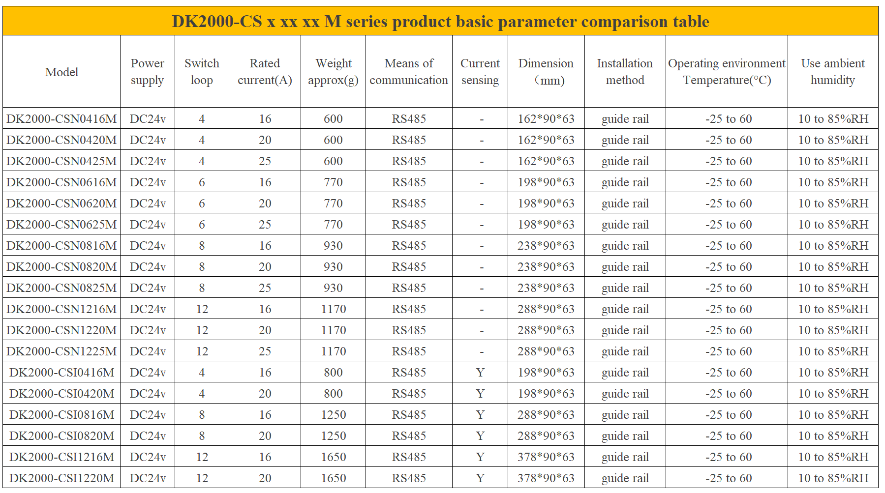
2-3 Product specifications and technical parameters
Power used/consumed: DC 24V / 1VA
Environment/Use: -25 to 60°C; 10 to 85% RH
Storage environment: -25 to 80 °C; Less than 90% RH
Man-machine interface: 12864LCD screen "menu/confirm", "up", "down", "left" and "right" buttons
Microprocessor: ARM series single chip microcomputer
All transmit and execute data to the upper controller
Independent monitoring application software is available to upload different application software according to different control requirements
All have the ability of self-diagnosis, real-time monitoring of the controller and loop, and upload to the host computer, to achieve centralized control
A battery-free program memory device (EEPROM) can store all operating programs to prevent data loss in the event of power failure.
All have extended FLASH, convenient system upgrade.
The guard dog device automatically resets.
Relay output: High power on/off capability magnetic holding relay.
Communication mode: 1xRS-485 1/2 duplex/Modbus RTU Protocol
Communication rate: 9600~76.8k bps (factory/recommended 9600 bps)
Maximum communication distance: 4000 ft (1.2 km) To ensure communication reliability, it is recommended that the communication distance be smaller than 600 m
Communication signal input: RS485 Modbus RTU
Communication address setting range: Up to 16, that is, a panel can be connected to a maximum of 16 controllers
Output specifications: Each loop can output A maximum of 16A/20A/25A three specifications
Communication signal connection head: 5PIN terminal
Appearance size: Without current detection function module size is as follows:
1) 4-way 16A/20A/25A: 162(W)*90(H)*63(D)
2) Route 6 16A/20A/25A: 198(W)*90(H)*63(D)
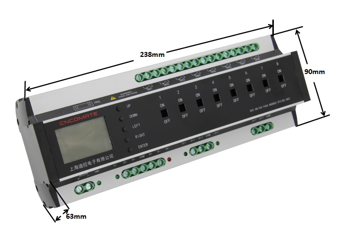
3) 8-way 16A/20A/25A: 238(W)*90(H)*63(D)
4)12 channel 16A/20A/25A: 288(W)*90(H)*63(D)
Dimensions of functional modules including current detection are as follows:
1)4 channels 16A/20A/25A: 198(W)*90(H)*63(D)
2) 8-way 16A/20A/25A: 288(W)*90(H)*63(D)
Installation: Standard DIN35 electric track
Weight: See the mapping table of basic parameters in the figure above
2-4 Advantages of magnetic holding controller compared with ordinary controller:
1. Large capacity magnetic holding relay is used to control circuit opening and closing. Compared with the ordinary relay, the power consumption is low and the calorific value is small.
2. It is suitable for situations with strict lighting requirements, such as hospitals, shopping malls, office buildings, schools, etc. When the control power cannot be guaranteed (failure), the magnetic holding relay can remain in the original state, or manually pull to force the closure/disconnection of each circuit, so as to ensure the normal operation of each circuit lighting.
3. With circuit current detection function, can monitor the circuit current in real time.
Note: With DK2000-OPT322 touch screen real-time monitoring loop current.
Click the "current view" button to enter the current view interface, as follows:
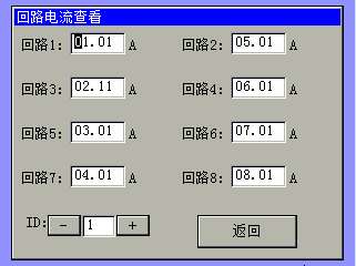
Note: The ID number is the address number of the controller to be mounted. If the controller to be mounted is set in the Parameter Setting interface before, the ID number is the address number of the controller to be mounted
The number of PI is n, so this number can only be 1 - n.
4. With the OPT322 screen, the loop current monitoring can set the loop abnormal alarm.
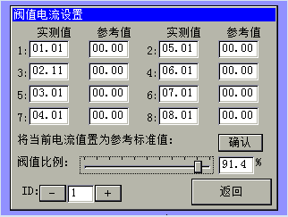
The setting function is to detect whether the load in the loop is damaged (such as light bulb). When the detected current is less than the ratio of the threshold value of the reference current, the corresponding loop will alarm to remind the staff to pay attention to, should check the line and deal with. The current current can be set as the reference current when the state current of each loop is normal. Current threshold percentage Users can evaluate the setting according to the nature and importance of the load.
5. With zero crossing disconnect function, ensure that when the loop is disconnected with load, the load is disconnected when the current value is close to 0A, play a good protective role for the relay contacts, and avoid the contact sintering (bad) as effectively as possible. The service life of relay is improved, thus the service life of controller is improved.
6. Adopt large capacity magnetic holding relay, resistive load rated current 50A, surge current up to 500A/2ms. Good load adaptability.
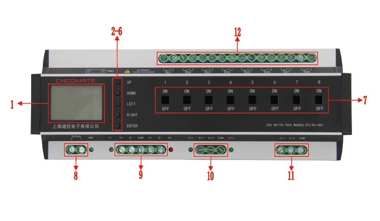
2-5 Dimensions and labeling of product shell
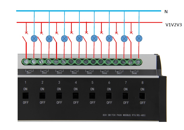
2-6 Keys and cable connection description
2-7 Controller hardware description
|
CSI0820M Controller hardware description |
|||
|
project |
name |
function |
remarks |
|
1 |
LCD screen |
Man-machine interface, display and set related functions |
|
|
2 |
Press Up |
Adjust the value/status of a set parameter |
|
|
3 |
Press Down |
|
|
|
4 |
Key Left |
Move the menu and select the desired menu item |
|
|
5 |
Key Right |
|
|
|
6 |
Press Enter |
The 'Confirm' button, when a menu or option is selected, will be backfired. |
|
|
7 |
The manual forced circuit back fails |
On-loop forced closure; OFF- The loop is forcibly disconnected |
To ensure safe operation, use a tool such as a driver |
|
8 |
Wiring terminal 24+, 24- |
Power DC24V input |
Power Power indicator. The indicator is on during normal operation |
|
9 |
Two groups of wiring terminals communicate D+,D-, and GND |
RS485 communication cable. D+ is connected to the communication line; D- Connect the communication line negative. One group in, one group out. |
Tx and Rx indicators. When the communication is normal, the two indicators blink |
|
10 |
Wiring terminals DI1, DI2, COM |
Passive switch input DI1,DI2, COM is the common terminal. |
When the switch quantity is closed and input, the corresponding indicator of DI1 and DI2 will light up |
|
11 |
Terminal AI1,AI2,AIG |
Analog signal input AI1,AI2, AIG is the common end. Input sources can be 0-10v,4-20mA, or NTC sources. |
Select source input mode by changing JP route position |
|
12 |
Terminal DO1-DO8 |
8 circuit switching output |
|
Please consult our relevant technical staff for details!