


Products & Applications
PRODUCTS

Intelligent scene panel
Location Position:Home > Products & Applications8-key multi-scene operation panel DK2000-OPB080

1-1 Overview of product features
Shanghai Dikong Electronics Co., Ltd. as a professional R & D, production, sales of intelligent lighting control system products of high-tech enterprises, we adopt the international advanced design concept to combine lighting control with network technology, create a highly comfortable environment and easy to manage network system platform, while saving daily operating costs, to achieve automatic control "E-, safer, more comfortable, more economical, efficient, expandable."and provide technical support for the integration of smart lighting control with third-party systems.
DK2000-OPB080 is an 8-key multi-scene operation panel, which is widely used in hotels, apartments, hotels, restaurants, shopping malls, hospitals, schools, theaters, gymnasiums, garages, road blocks, etc. It can be combined with computers, network web servers, dimming controllers, lighting switch controllers and other sensors such as illuminance, human body sensing sensors, etc. to form a complete intelligent lighting control system.
1. Eight illuminated indicator buttons support user-defined lettering.
2. Use DIP switches to set the local address and the number of lower controllers.
3. Equipped with lock key and unlock function.
4. The communication protocol adopts the standard open RS485 MODBUS RTU 16-bit, which can realize the accurate exchange of data between the entire system equipment. In consultation with DiHoldings, integration with third-party systems is also possible.
5. 8 scene keys, you can configure the key call area scene, dimming and properties according to your needs.
6. It can be used with Ethernet integrated host equipment, web network web server controller and web server to realize computer remote monitoring.
1-2 Product specifications and characteristics
Power consumption: DC 24V / 1VA
Environment / Use: - 10 to 45 °C; 10 to 85% RH
Storage environment: -10 to 90 °C; Less than 90% RH
Microprocessor: ARM series monolithic microcomputer
Transfer and execute data to the higher-level controller
There are independent monitoring application software, which can easily upload different application software according to different control requirements
It has self-diagnosis ability, real-time monitoring of the controller and loop, and upload to the host computer to achieve centralized control
There is a battery-free program memory device (EEPROM) that stores all operating programs to prevent data loss in the event of a power failure.
Expanded FLASH for easy system upgrades.
Watchdog device Automatic reversion.
Communication: 1 x RS-485 1/2 duplex / Modbus RTU Protocol (communication protocol).
Communication rate: 9600~76.8K bps (factory in-house / recommended 9600 bps).
Maximum communication distance: 4000 ft (1.2 km).
Communication signal input: Modbus RTU
Mailing address range: 1-16
Communication signal connector: 6PIN terminal.
Dimensions: 86 mm x 86 mm x 32mm
Installation: Standard 86 box installation
Weight: 80 g (net).
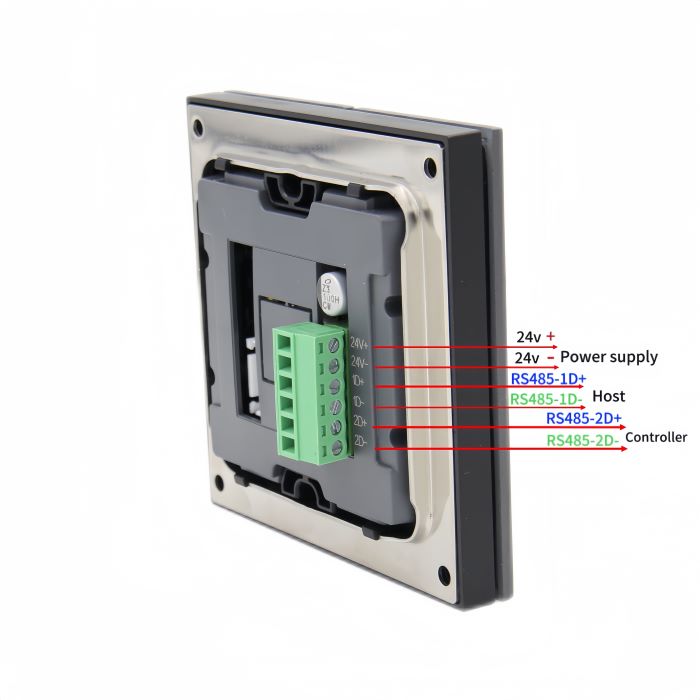
1-3 Hardware & Wiring Instructions

2 Operating Instructions
2-1 The local ID address is set
The setting of the local ID address is set by the 'ADD' DIP switch, open the upper cover panel of the product to see the two DIP switches 'ADD' and 'CON_CU', and set the address in the system framework by toggling the 1,2,3,4 switch on the DIP switch 'ADD'
 Note: Duplicate addresses cannot appear on the same RS485 communication line.
2-2 Set the number of controllers to be attached
The number of controllers under the machine is set by the 'CON_CU' DIP switch, open the upper cover panel of the product can see two DIP switches 'ADD' and 'CON_CU', by toggling the 1,2,3,4 switch on the DIP switch 'CON_CU' to set the number of controllers under the machine in the system framework:
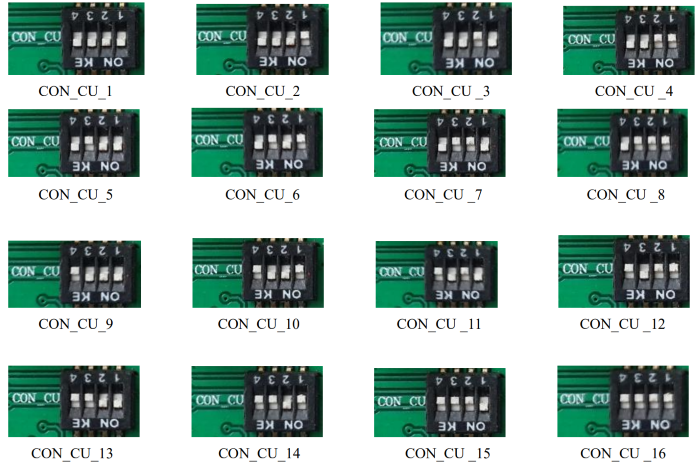 Note: The actual number of controllers should be consistent with the value set by the dial code, for example, if there are 5 controllers under the 1# panel, the maximum CON-CU value should be set to 5.
2-3 Scene calls
8 buttons, corresponding to Scene 1, Scene 2, Scene 3, Scene 4, Scene 5, Scene 6, Scene 7, Scene 8, when the corresponding scene button is pressed, the corresponding scene in the controller will be called.
The 8 scene keys are interlocked, when one scene is called, another scene is called, and the scene will replace the previous scene.
When a scene key is pressed, the scene key will glow white, indicating that the scene has been successfully invoked, and if the scene key is pressed again, the scene will be closed and the key indicator will be turned off.
In the case of a single-bus system, each button can be configured according to the user's needs, such as regional scenes, dimming and dimming properties.
Note: For the scene stored by the controller, the staff needs to complete the scene editing and save it on the controller before calling. For details about how to edit the scene, please refer to the controller product manual.
2-4 Key/unlock
After the panel operation is completed, in order to prevent human misoperation, you can operate the key combination to lock the key: '7' + '8' press at the same time for more than 2s, all key functions will be locked (the operation function button will not perform any operation). Operate the same key combination as in the lock key state: '7' + '8' press at the same time for more than 2s, and the key will be unlocked at this time.