


Products & Applications
PRODUCTS

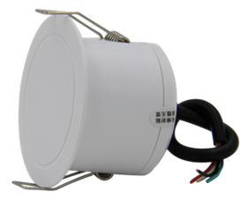
Sensor and accessories
Location Position:Home > Products & ApplicationsDK2000-MTDx61-RC Dry contact series Human presence sensors
1.1 Main parameters


1.2 Detection range: top mounting
The figure below shows a rough diagram of the detectable area of the sensor when "top mounted".
(1) "Breathing" (standing, squatting, sitting, sleeping, etc.);
(2) "Micro-motion" detection area: It can detect micro-movement (tilting, waving, raising, getting up, flipping the book, body shaking left and right, back and forth, etc.);
(3) "Movement" (walking, trotting, brisk running, spinning, jumping, etc.);

2. The detectable radius is related to many factors such as the installation environment, the body shape of the person, the relative angle, and the amplitude of the micro-movement/motion action, the above parameters are the test results of the sensor used by our testers, and the descriptions of small movements and movements are qualitative descriptions, not quantitative descriptions, for reference only. Under different test conditions, please refer to the actual test.
2. Interface size
2.1 Interface

2.2 Size
DK2000-MTDx61 dry contact series sensor is embedded in the ceiling installation method, and the outer edge of the sensor is 50mm; The dimensions of the embedded ceiling part are: diameter × height = 40×35mm.

2.3 Connection
External power and signal cables are connected to the sensor's built-in wiring harness and introduced into the ceiling cutout.

3.1 Installation method 1:Flush mounting
1. According to the scope and shape of the area to be inspected, select a suitable installation position on the ceiling to ensure that the detection area can be effectively covered.
2. The diameter of the edge of the equipment is 50mm, the embedded part is 40*35mm (cylinder), the diameter of the round hole can be opened on the ceiling is 40-42mm, and the minimum reserved space at the top is not less than 50mm.
3. Clamp the power supply and signal cables on the equipment (lightly clamp the wires, otherwise the wires are easy to be clipped) and introduce them into the ceiling openings.
4. Snap the device into the ceiling hole to complete the installation.

1. According to the scope and shape of the area to be inspected, select a suitable installation position on the wall to ensure that the detection area can be effectively covered.
2. The sensor is fixed on the mounting bracket, and according to the installation angle of the sensor, a wire harness perforation and a bracket fixing hole are made in the wall, and the wire harness through hole is a round hole with a diameter of 8mm.
3. The diameter of the fixing hole of the equipment mounting bracket is 5mm, and a round hole with a diameter of 5mm can be opened on the wall, and the bracket is fixed with matching expansion screws, and the minimum reserved space at the top is not less than 50mm.
4. Introduce the power supply and signal cables into the bracket opening, and clamp them on the wiring harness reserved by the equipment (lightly clamp the wire, otherwise the wire is easy to be clamped) to complete the installation.


4. Product Usage
4.1 The output signal is connected to the user's system
The reed output S1 and S2 terminals of the sensor are connected to the user system; Select the appropriate access solution based on your specific situation:
(1) Four-wire fully isolated access mode:
The S1 and S2 terminals are not electrically connected to the sensor. When the presence of a human body is detected, the S1 and S2 terminals are switched on; Otherwise, the S1 and S2 terminals are disconnected;
Tip: See the "Reed Output Signal Description" section of the "Order Selection" section
4.2 Sensor powered
9 V, DC power supply for sensors with the suffix DC; Provide 9~24 V, DC power supply for sensors with suffix RC; The DC power supply can be centrally powered using a switching power supply, or it can be powered separately using a power adapter.
4.3 Installation principles
(1) Entryway/aisle, dressing room scene: centered, firmly fixed.
(2) Kitchen scene: centered, securely fixed. If the installation area is rectangular and there is a glass door on the long side, if the central installation position is just facing the position of the glass door, you need to re-select the position, then you can solve the problem of penetrating the door by installing the sensor on the side of the solid wall on the side of the door, and the experience will not be affected after setting the appropriate distance.
(3) Family bathroom and toilet scene: away from doors and windows, away from exhaust fans; 0.4-0.6m in front of the top of the toilet/squatting position, it is necessary to take into account that the set detection distance can cover the entire scene space, and the microwave signal can penetrate the glass door or wooden door, and the problem of penetrating the door can be solved by installing the sensor on the side of the solid wall on the side of the door, and the actual positioning needs to be comprehensively evaluated on site.
(4) Living room/dining room/meeting room scene: living room: 0.5~1m in front of the sofa; Dining room: table center; Meeting room: On the central axis on the long side of the conference table.
(5) Bedroom, study scene: bedroom: the area directly above the bed; Study: within 0.6-1.5m before and after the desk.
(6) Other types of scenarios
① Narrow and special-shaped area scenario: The long side of the long side of the long side of the narrow area (the long side is less than 10 m) is a solid wall on both sides, which can be installed in the center; If one of the long sides is a glass partition or gypsum board partition, and the long side is less than 1.3 times that of the short side, you can choose to install it by the center point of the solid wall, if it is greater than 1.3 times, it is necessary to install 2 sensors in the center to cover it; if the long side is a glass partition or gypsum board partition, two sensors need to be covered in the center; the long side of the narrow area is much larger than the area that the sensor can cover, and the area needs to be divided and the above principles are observed.
② Glass and gypsum board partitions: Stay away from glass and partitions, and try to get as close to a solid wall as possible under the premise that the sensor can meet the breathing area that needs to be covered. If the perimeter is all glass and partition are installed in the center, and the appropriate detection distance, indentation distance, and trigger sensitivity are set to solve the situation that the outside of the glass and the wall are detected.
③ People sitting, squatting, standing still: the sensor is mounted on top, 0.4-0.8m in front of the front of the top of the person's head. It is not advisable to install it directly on the top of the head.
④ Dense deployment scenario: During intensive deployment, the straight-line separation distance of the sensor is not less than 4 m.
4.4 Common sources of interference and solutions
(1) Fans: Fans with moving heads (blade diameter greater than 10cm), metal blade fans without shaking heads, ceiling fans.
If the fan blade is larger than 10cm, the fan head head can make the sensor that triggers the manned state continuously output the manned state within the respiratory detection range; The non-moving metal fan triggers or maintains the sensor's manned output when it is working; The non-moving plastic fan can be filtered by the sensor in areas other than breath detection. Setting the appropriate trigger sensitivity can effectively avoid partial interference, trigger sensor output manned.
(2) Air conditioning: the wind pendulum of hang-up and cabinet machine, the metal ornaments blown by the air conditioner, the thick curtains blown by the air conditioner, the ceiling vibration driven by the ceiling air conditioner, and the louver vibration of the central air conditioner.
The wind swing and louver vibration of the air conditioner are within the breathing coverage of the sensor, which can trigger or maintain the sensor manned state; The large amplitude of greenery blown by the air conditioner can also trigger or maintain the presence of the sensor. Setting appropriate trigger sensitivity and trigger indentation can avoid most of the false triggers; However, it cannot completely solve the problem that after the person leaves, the interference causes the sensor to continuously output the manned state.
(3) Curtains: curtains with large fluctuations, roller blinds with aluminum alloy lower rails.
Curtains with small swings such as cloth, cotton, and sand curtains used in ordinary households are not easy to trigger the sensor; Roller blinds with aluminium lower rails can easily trigger the sensor if they swing within the detection range. By setting an appropriate detection distance to filter out such interference, false triggering caused by the above scenarios can be well avoided.
(4) Exhaust fan: Ceiling vibration caused by metal fan blades and exhaust fans of exhaust fans. If the front of the sensor is not irradiated by the diameter of the fan blade sensor and cannot be triggered, the ceiling vibration caused by the exhaust fan will cause the sensor to vibrate or the sensor will detect the vibration surface will be triggered.
Avoid exhaust fans or vibrating surfaces within the detection distance of the sensor; Fix the exhaust fan to avoid vibration of the ceiling.
(5) Strong 5.8GHz WiFi signal interference: There is a 5.8GHz WiFi router/AP within 3m of the front area of the sensor; Or there is a 5.8GHz WiFi router/AP in the horizontal direction or within 1.5m on the back of the sensor.
It is recommended that the WiFi router in the front area of the sensor be installed more than 3m away from the sensor; For routers in other directions, the distance between the mounting position and the sensor is at least 1.5 m, and when using a top-mounted AP, the distance between the AP and the sensor is at least 1.5 m.
(6) Airflow (wind): Objects in the scene may move, flutter, vibrate, etc. caused by blowing, which may be triggered.
Setting the appropriate trigger sensitivity can filter the wind and grass below level 2-3, and the larger the wind level, the easier it is to trigger by mistake.
(7) Animals: cats, dogs, mice, other pets, etc. The difference between other animal and human characteristics is that the triggering mechanism is the same as that of a human, such as the size of an animal and a human.
Set the appropriate trigger sensitivity and trigger indentation distance, most cats, puppies and mice cannot trigger the sensor. For example, large swings of curtains caused by cats and dogs, or dragging, or dragging, moving objects, etc., can also trigger the sensor.
(8) Low-frequency vibration: wall or ceiling vibration caused by loud audio volume, vibration caused by upstairs and downstairs decoration, etc.
When installing, it is necessary to keep a suitable distance from the speaker to avoid the radar signal directly irradiating the main speaker, and when choosing the installation location, the main consideration is to cover the area where people are stationary, such as sofas, seats, etc. Set the sensitivity relatively low (to avoid false triggering) and a longer 'manned to unmanned delay' for more reliable detection.