


Products & Applications
PRODUCTS

Dimming control module
Location Position:Home > Products & Applications6-way 0~10V/PWM dimming controller DK2000-CDA0616M
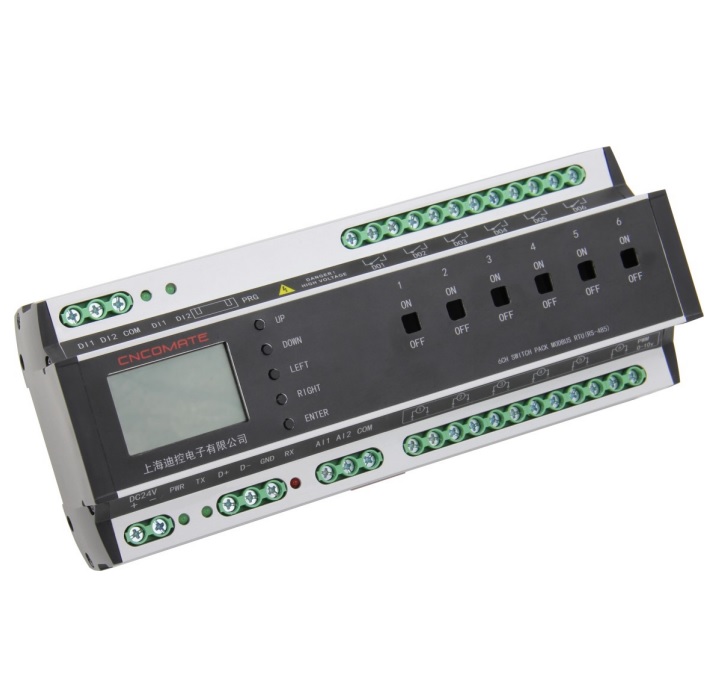
2-1 Product overview
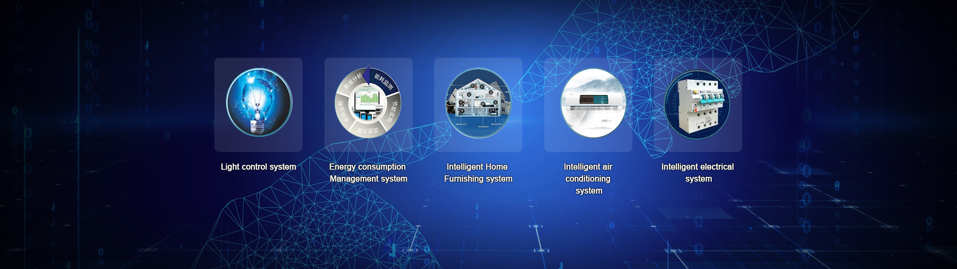
DK2000-CDA0616M is an intelligent 0~10V dimming module with Chinese and English menu interface, no programming, which can be used after the user sets parameters independently. The main loop adopts magnetic holding relay output, low power consumption, high reliability, when the luminance is lower than 5% (default value), the luminance will automatically cut off the power supply. To make users safer and more energy efficient; The 0~10V dimming circuit has two output modes: DC 0/1-10V and PWM, which can support all kinds of brands on the market. For hotels, restaurants, shopping malls, hospitals, schools, theaters, stadiums, factories, tunnels and other places to achieve brightness regulation; It can also be combined with computer, WEB embedded web server, intelligent scene panel and other kinds of sensors such as illumination, human body sensing PIR and so on to form a complete intelligent lighting control system.
2-2 System networking diagram:

2-3 Product Functions and Features:
1. Use aluminum alloy shell to improve heat dissipation and protection performance.
2. Chinese LCD screen: menu-type Chinese interface, can be combined with function keys, very convenient to do the parameter setting and scene call functions.
3. 50A magnetic holding relay is adopted in the switching loop: low power consumption, low heat, high reliability, surge resistance current up to 500A.
4. The kinetic energy of each 0~10V tuner can reach 200mA or above, and three dimming modes are optional :DC0/1-10v and PWM.
5. Longitude and latitude time control and timing function: it can automatically call different lighting modes with the time of sunrise and sunset throughout the year.
6. Automatic control function is realized according to illumination and human body sensing: multifunctional sensor (illumination and human body moving PIR) can be realized.
7. All fire alarm linkage control function: when receiving the fire strong start signal, all emergency lighting circuits are forced to open.
8. Reserve 2 groups of switching quantity and 2 groups of analog quantity signal input port: according to user needs, to achieve specific functional requirements.
9. Can be set dimming circuit fade in and out time :1S-99S adjustable, that is, can be instantly lit, can also slowly light, slowly dim.
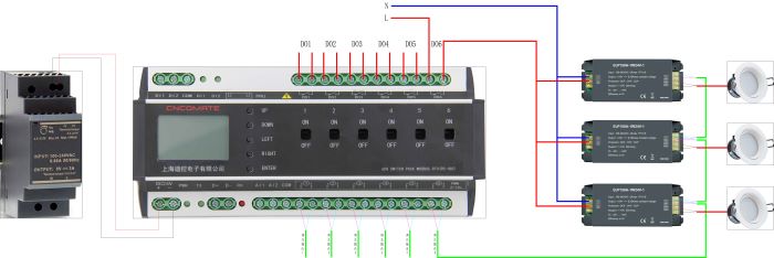
2-4 Wiring diagram for product use
2-5 Product specifications and technical parameters
Power consumption: DC 24V / 6VA
Environment/Use: -25 to 60°C; 10 to 85% RH
Storage environment: -25 to 80 °C; Less than 90% RH
Man-machine interface: 12864LCD screen "menu/confirm", "up", "down", "left" and "right" buttons
Microprocessor: ARM series single chip microcomputer watchdog device automatic return.
Relay output: 50A high power magnetic holding relay.
Communication mode: 1xRS-485 1/2 duplex/Modbus RTU Protocol
Communication speed: 9600~76.8k bps (factory/recommended 9600 bps)
Maximum communication distance: 4000 ft (1.2 km).
Communication signal input: RS485 Modbus RTU
Communication address setting range: Up to 16, that is, a panel can be connected to a maximum of 16 controllers (32 can be customized)
Drive capacity: Each 0~10V dimming circuit, single channel is not less than 200mA (leading in the industry)
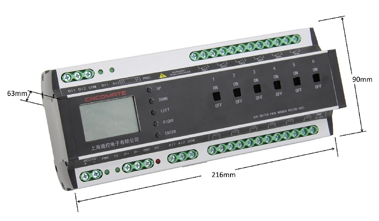
Dimensions: 1) 4-way dimming driver module: 216 mm x 90 mm x 63mm
2) 6-way dimming driver module: 216 mm x 90 mm x 63mm
3) 8-way dimming driver module: 244 mm x 90 mm x 63mm
Installation: Standard DIN35 electric track
Weight: 4-way about 600g;6-way about 600g;8-way about 770g;
2-6 Product size drawing:
2-7 Hardware description of the dimmer module

|
DK2000-CDA0616M Controller hardware description |
|||
|
project |
name |
function |
remarks |
|
1 |
LCD screen |
Man-machine interface, display and set related functions |
|
|
2 |
Press Up |
Adjust the value/status of a set parameter |
|
|
3 |
Press Down |
|
|
|
4 |
Key Left |
Move the menu and select the desired menu item |
|
|
5 |
Key Right |
|
|
|
6 |
Press Enter |
The 'Confirm' button, when a menu or option is selected, will be backfired. |
|
|
7 |
The manual forced circuit back fails |
On-loop forced closure; OFF- The loop is forcibly disconnected |
|
|
8 |
Wiring terminal 24+, 24- |
Power DC24V input |
Power Power indicator. The indicator is on during normal operation |
|
9 |
Wiring terminal D+,D-,GND |
RS485 communication cable. D+ is connected to the communication line; D- Connects to the negative communication cable,GND grounding |
Tx and Rx indicators. When the communication is normal, the two indicators blink |
|
10 |
Terminal AI1,AI2,AIG |
Analog signal input AI1,AI2, AIG is the common end. Input source can be 0-10v, or NTC signal source. |
Select source input mode by changing JP route position |
|
11 |
Terminal AO1-AO6 |
6 Circuit dimming signal output. |
DC0/1-10v, PWM |
|
12 |
Terminal DI1, DI2, COM terminal |
Passive switch input DI1,DI2, COM is the common terminal |
When the switch quantity is closed and input, the corresponding indicator of DI1 and DI2 will light up |
|
13 |
DO1-DO6 |
6 Loop switch output |
|