


Products & Applications
PRODUCTS

Dimming control module
Location Position:Home > Products & Applications12 circuit 10A high-power front dimmer box
2 -1 Product introduction
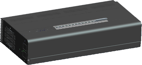
Frontier power dimmer through input 0/1-10V signal, can be incandescent lamp, 220V halogen lamp, and equipped with adjustable optoelectronic transformer low-voltage halogen lamp dimming, power dimmer single loop output power can reach 2KW.
Model: DK2000-CDV1210L
Power supply: AC 380V
Control signal input: 0/1-10V
Output: 220V 50HZ
Output power: 2KW * 12 channels
2 -2 Product characteristics
-
0/1-10V low voltage control, safer
-
Multiple temperature protection, safe and reliable
-
Dimming output is stable, rise time ≥200us
-
Hanging type installation, convenient construction
-
When the temperature reaches 75±5°C, the output brightness is reduced by half
-
When the temperature reaches 85±5°C, turn off the output of the dimmer
-
There are feeding holes on the upper, lower and back to adapt to various feeding methods
-
Three-phase or single power supply can be used
-
Equipped with manual automatic switch, manual switch and dimming
2 -3 Technical parameter
Model DK2000-CDV1210L Dimming rise time 220us in 220V
Power supply voltage 380V, 50HZ external size 630*320* 130mm
Signal input 0/1-10V Weight 17.8KG
The minimum load is 60W
Output load 0-220V shell material, color iron, black
Power output 2KW*12 Protection IP 20, EN 60 529
Output current 10A*12 Standard CE UL
Terminal wire diameter: 2.5-4.0 mm2 Operating temperature range 0 -- +45°C
Type of load


2-4Mounting size (mm)

2 -5 Wiring terminal
DK2000-CDV1210L Controller hardware description
project
name
function
remarks
1
L1
AC380V Firewire input
2
L2
AC380V Firewire input
3
L3
AC380V Firewire input
4
N
Zero line input
5 to 16
1-12 group dimming output
Twelve 220V dimming output circuits
17
Signal input 0/1-10V
Input 0/1-10V signal
18
Ground wire
ground
19
Indicator light
The indicator lights up during normal operation
20
Manual dimming
Manual dimming output
0/1-10V low voltage control, safer
Multiple temperature protection, safe and reliable
Dimming output is stable, rise time ≥200us
Hanging type installation, convenient construction
When the temperature reaches 75±5°C, the output brightness is reduced by half
When the temperature reaches 85±5°C, turn off the output of the dimmer
There are feeding holes on the upper, lower and back to adapt to various feeding methods
Three-phase or single power supply can be used
Equipped with manual automatic switch, manual switch and dimming
DK2000-CDV1210L Controller hardware description
project
name
function
remarks
1
L1
AC380V Firewire input
2
L2
AC380V Firewire input
3
L3
AC380V Firewire input
4
N
Zero line input
5 to 16
1-12 group dimming output
Twelve 220V dimming output circuits
17
Signal input 0/1-10V
Input 0/1-10V signal
18
Ground wire
ground
19
Indicator light
The indicator lights up during normal operation
20
Manual dimming
Manual dimming output
2 -6 Wiring diagram

2 -7 Installation and debugging
-
Wiring specification
-
Power phase cable: red 2.5-4mm2 copper conductor
Neutral wire: light blue 2.5-4mm2 copper conductor
Ground cable: yellow and green 2.5mm2 copper conductor
-
Load cable: Copper conductor with more than 4mm2
-
0/1-10V: 1.0 to 1.5mm2 shielded twisted pair cable
-
Open the product package, take out the paper pattern in the package, drill holes in the bearing wall, install expansion screws, and then fix the power dimmer on the wall
-
Connect each input terminal, output terminal, 0/1-10V terminal according to the wiring diagram
-
When three-phase power balance is satisfied, single-phase power supply can also be used for input power supply, and the input line of a single power supply is connected to three input terminals at the same time (input terminals in parallel).
-
When powered on, the indicator light (19) blinks. Press the 1-12 keys corresponding to (20) on the panel to output 1-12 channels of dimming respectively. When the key is held down, it is dimming. Manual state is priority, did not exit manual state, 0/1-10V signal cannot control the device. When the first group signal input terminal (A) of the signal input terminal (17) inputs 0/1-10V signals, the corresponding output terminal (5) will output a corresponding AC voltage in the first circuit. A---L is 0/1-10V signal terminals corresponding to 5-16 AC output terminals.
For details, please consult our technical staff!
Wiring specification
Power phase cable: red 2.5-4mm2 copper conductor
Neutral wire: light blue 2.5-4mm2 copper conductor
Ground cable: yellow and green 2.5mm2 copper conductor
Load cable: Copper conductor with more than 4mm2
0/1-10V: 1.0 to 1.5mm2 shielded twisted pair cable
Open the product package, take out the paper pattern in the package, drill holes in the bearing wall, install expansion screws, and then fix the power dimmer on the wall
Connect each input terminal, output terminal, 0/1-10V terminal according to the wiring diagram
When three-phase power balance is satisfied, single-phase power supply can also be used for input power supply, and the input line of a single power supply is connected to three input terminals at the same time (input terminals in parallel).
When powered on, the indicator light (19) blinks. Press the 1-12 keys corresponding to (20) on the panel to output 1-12 channels of dimming respectively. When the key is held down, it is dimming. Manual state is priority, did not exit manual state, 0/1-10V signal cannot control the device. When the first group signal input terminal (A) of the signal input terminal (17) inputs 0/1-10V signals, the corresponding output terminal (5) will output a corresponding AC voltage in the first circuit. A---L is 0/1-10V signal terminals corresponding to 5-16 AC output terminals.